
Flangers and Phasers
Q: What is the difference between a flanger and a phaser?
A: Flangers and phasers are fundamentally the same thing: an element that creates time-varying phase delay, surrounded by feedback. Figure 1, below, shows a block diagram for a flanger or phaser. The phase-delay element can be viewed generically as an all-pass filter (see last month's column for a discussion of all-pass filters); this element is a linear system that has unity gain at all frequencies. The phase response of the element is nonzero, and varies as a function of time. Usually, the time variation is effected by an LFO (low-frequency oscillator).

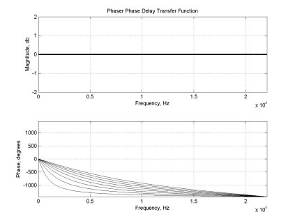
Figures 2 and 3, below, show magnitude and phase responses for phase-delay elements used in flangers and phasers, respectively. Because the phase-delay element varies over time, both plots show multiple traces. Each trace shows the behavior of the element at a single instant. For the flanger, it can be seen that the element is equivalent to a pure delay, or a linear-phase system. A continuous-time system with this response could be represented by the transfer function e-ds, while in discrete-time it would be written z-δn. Here “d” or δ is used to represent the amount of delay exhibited by the element. For the phaser, the phase-delay element is not linear phase. Instead, it is usually constructed as a cascade of anywhere from four to sixteen first-order all-pass filters. For continuous-time systems, this element would have the transfer function [(s-a)/(s+a)]n, or in discrete-time, [(α-z-1)/(1-αz-1)]n. In both cases, "n" is the number of first-order filters, and “a” (or α) is related to the all-pass filter's characteristic frequency.
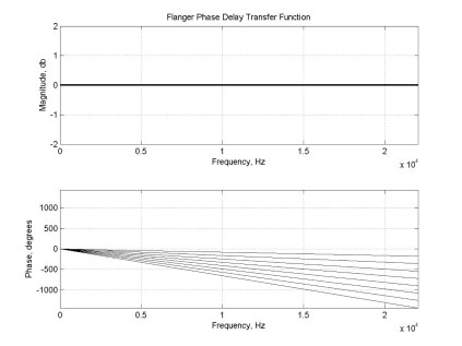
The flanger tends to have a “pitched” sound. By contrast, the phaser's peak locations are not harmonically related. This results in a more “windy,” less pitched sound.
For both the flanger and phaser, the effective delays encountered when passing through the phase-delay elements are small enough to be perceptually unimportant in the absence of feedback; without feedback, the elements will sound close to neutral. However, with the addition of feedback, the overall magnitude transfer functions of these systems will no longer be flat. Depending on the sign of the feedback, frequencies at which the phase of the delay elements approaches odd or even multiples of π will produce peaks in the transfer function. The strength of the peaks will be determined by the amount of feedback used. Figures 4 and 5, below, show “closed-loop” magnitude transfer functions for the flanger and phaser at a single instant in time. As the phase delay elements vary over time, the peaks shown in these plots will move up and down in frequency.
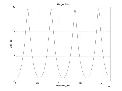
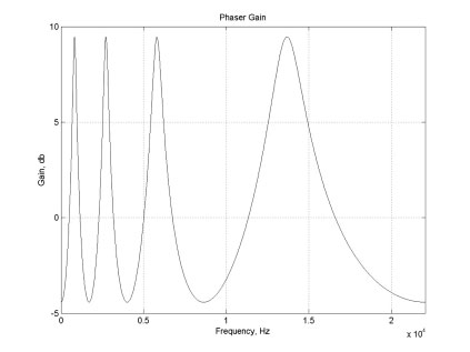
As can be seen, the peaks in the flanger's transfer function are equally spaced in frequency. This is due to the delay element's linear phase: because the phase function is a straight line, it crosses multiples of π at equally spaced intervals. By contrast, the phaser's transfer function has peaks that are spaced unevenly. This reflects the non-linear phase curve associated with the chain of all-pass filters.
The even spacing of the flanger's peaks gives it a resonance; all peaks are located at harmonics of a particular frequency. Because of this, the flanger tends to have a “pitched” sound. By contrast, the phaser's peak locations are not harmonically related. This results in a more “windy,” less pitched sound.
For both the flanger and phaser, the phase delays produced by the all-pass networks are relatively small. Neither effect produces enough delay to be perceived in the time domain, and the phase response varies slowly enough to prevent noticeable pitch deflection. A related effect, the chorus, is structurally identical to the flanger. However, the chorus has a relatively long delay element. When this element varies over time, the change in delay is sufficient to produce a doppler-like frequency deflection which can be perceived. The long delay used in the chorus also results in a very dense arrangement of spectral peaks (in general, the number of peaks in the spectrum is roughly proportional to the number of samples of delay used). For the chorus, the peaks in the spectrum are too dense to be perceived as resonances. So, for the flanger and phaser, the main perceived effect is that of a time-varying resonance, while for the chorus, the pitch deflection is more obvious.
The flanger, phaser and chorus are three effects built from the same topology. Differences in alignment of resonances separate the flanger and phaser, and length of the delays involved separate the flanger from the chorus.
— Dr. Dave Berners
続きを読む

Allpass Filters
A: Allpass filters are filters that have what we call a flat frequency response; they neither emphasize nor de-emphasize any part of the spectrum.